STP VS RSTP
The following table outlines the main differences between Rapid STP (802.1w) and the legacy STP(802.1d):
| STP (802.1d) |
Rapid STP (802.1w)
|
| In stable topology only the root sends BPDU and relayed by others. | In stable topology all
bridges generate BPDU every Hello (2 sec) : used as “keepalives” mechanism. |
| Port states |
| DisabledBlockingListeningLearningForwarding | Discarding (replaces disabled, blocking and listening)
LearningForwarding |
| To avoid flapping, it takes 3 seconds for a port to migrate from one protocol to another (STP / RSTP) in a mixed segment. |
| Port roles |
Root (Forwarding)
Designated (Forwarding)
Non-Designated (Blocking) | Root (Forwarding)
Designated (Forwarding)
Alternate(Discarding)Backup (Discarding) |
| Additional configuration to make an end node port a port fast (in case a BPDU is received). | – An edge port (end node port) is an integrated Link type which depends on the duplex : Point-to-point for full duplex & shared for half duplex). |
| Topology changes and convergence |
Use timers for convergence (advertised by the root):
Hello(2 sec)
Max Age(20 sec = 10 missed hellos)
Forward delay timer (15 sec) | – Introduce proposal and agreement process for synchronization (< 1 sec).- Hello, Max Age and Forward delay timer used only for backward compatibility with standard STP |
| Only RSTP port receiving STP (802.1d) messages will behaves as standard STP. |
Slow transition (50sec):
Blocking (20s) =>Listening (15s) =>Learning (15s) =>Forwarding | Faster transition on point-to-point and edge ports only:Less states – No learning state, doesn’t wait to be informed by others, instead, actively looks for possible failure by RLQ (Request Link Query) a feedback mechanism. |
| Use only 2 bits from the flag octet:Bit 7 : Topology Change Acknowledgment.Bit 0 : Topology Change | Use other 6 bits of the flag octet (BPDU type 2/version 2):
Bit 1 : ProposalBit 2, 3 : Port roleBit 4 : LearningBit 5 : ForwardingBit 6 : AgreementBit 0, 7 : TCA & TCN for backward compatibility |
| The bridge that discover a change in the network inform the root, that in turns informs all others by sending BPDU with TCA bit set and instruct them to clear their DB entries after “short timer” (~Forward delay) expire. | TC is flooded through the network, every bridge generate TC (Topology change) and inform its neighbors when it is aware of a topology change and immediately delete old DB entries. |
| If a non-root bridge doesn’t receive Hello for 10*Hello (advertised from the root), start claiming the root role by generating its own Hello. | Wait for 3*Hello on a root port (advertised from the root) before deciding to act. |
| Wait until TC reach the root + short timer (~Forward delay) expires, then flash all root DB entries | Delete immediately local DB except MAC of the port receiving the topology changes (proposal) |
Difference between STP and RSTP
1. in STP 3 states Discarding,Learning and Forwarding but in the STP 5 states
2. in STP convergence takes too long (with default timers). But in the RSTP convergence is fast
Example:
STP
-----
The hello time is 2 seconds. The Max Age Timer is 10x the the hello timer. This is important. Because it's not always 20 seconds, it's 20 seconds because the hello timer is 2 seconds.
STP has 4 states: blocking, listening, learning and then forwarding.
Once a port is in blocking state, it stays there for 20 seconds. Then moves onto listening at 15 seconds, then learning at 15 seconds. That's where you get your 50 seconds.
·
Direct failure— A direct
failure is detected immediately and enables a switch to immediately expire the
Max Age timer, invalidating all current configuration BPDUs. At this point, the
switch announces itself as the root bridge and must pass through the Listening
and Learning phases before forwarding traffic. Because the forward delay timer
determines how long the Listening and Learning phases are, the convergence time
for a direct failure is defined as 2 x forward delay. For example, if the
forward delay timer is the standard 15 seconds, the convergence time of a
direct failure will be 2 x 15 seconds or 30 seconds.
Indirect failure— An indirect failure is not detected
immediately and relies upon configuration BPDUs not being received for the
duration of the Max Age timer. Once the Max Age timer expires, the root bridge
is considered down, and the switch will announce itself as the root bridge and
must pass through the listening and learning phases before forwarding traffic.
The convergence time for an indirect failure can be calculated as the Max age
timer + 2 x forward delay. For example, if using the default STP timers, the
convergence time of an indirect failure is 20 + (2 * 15) seconds or 50 seconds
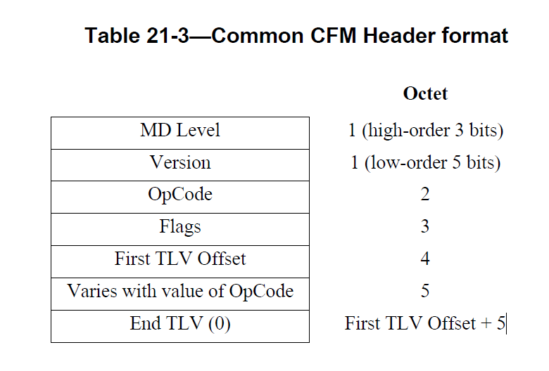
BPDU format:


RSTP
------
The max age is 3x the hello. So a max of 6 seconds. There's no blocking port in RSTP. It's discarding state. Discarding replaces blocking and listening. So you only have discarding, learning and forwarding.
RSTP convergece full explanation: http://swavijay.blogspot.in/2012/05/understanding-rstp-convergence.html?view=flipcard
- it additoinally has propoposal and agreement for fast convergence
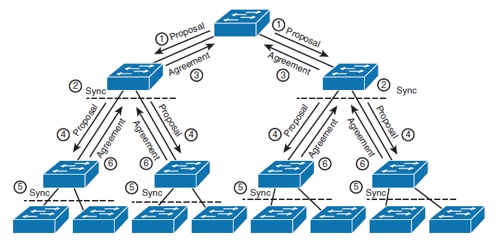
Topology events can occur when a new switch is plugged into the existing switching infrastructure. RSTP uses a Proposal/Agreement process on point-to-point links to rapidly put the port into a forwarding state without causing a disruption in services or creating a loop.
The Proposal signifies the willingness of a port to become Designated Forwarding….while the Agreement stands for allowing the port to begin forwarding immediately.
When a new point-to-point link is added between two switches, both ports come up as Designated Discarding, the default role. Ports in the Discarding or Learning state send BPDUs with the Proposal bit set, both switches will do this assuming they have the right to be Designated.
If the BPDU received on the designated discarding port is determined to be the superior BPDU its role will change from Designated to Root discarding. Port roles will also be updated in the process.
If a switch receives a BPDU with a proposal bit set on its Root port, it places all non-edge ports into a discarding state…this operation is called Sync. A switch in Sync state is isolated from the network, preventing any loops from passing through it.
Once it is syncd the switch moves the new Root port into a Forwarding state and informs the upstream switch that it is now allowed to move its designated discarding or learning port to a forwarding state. This is done by the switch sending a BPDU with the Agreement bit set through its Root Port after performing the Sync.
After receiving the Agreement the upstream switch will move the port into a forwarding state completing the Proposal/Agreement Process
As a result all designated non-edge ports were put into a discarding state, at this point they all begin sending BPDUs with the Proposal bit set and begin the Proposal/Agreement process downstream to the other switches.
Ref: https://www.youtube.com/watch?v=Pbv2wLQ2xyY
https://cciethebeginning.wordpress.com/2008/11/20/differences-between-stp-and-rstp/
http://www.omnisecu.com/cisco-certified-network-associate-ccna/difference-between-stp-and-rstp.php
https://bethepacketsite.wordpress.com/2016/02/29/spanning-tree-protocol-rstp-proposalagreement-process/
STP TIMERS:
Spanning-tree timers are important because they determine how
quickly or slowly a spanning-tree topology can react to a link or bridge
failure and converge to a new topology. As indicated in Table 4-1, there are
three spanning-tree timers:
·
Hello timer— The
interval at which each configuration BPDU is generated. The default is two
seconds, meaning that a configuration BPDU is generated every two seconds.
·
Max age timer— Controls
how long a configuration BPDU is valid after being received. The default is 20
seconds, meaning that if a configuration BPDU is not received within 20 seconds
of the previous, the previous configuration BPDU is no longer valid and a new
root bridge must be selected.
·
Forward delay— Controls
the amount of time that a bridge port spends in each of the Listening and Learning phases before transitioning a blocking
port to a Forwarding state.
Convergence timer:
·
immediately expire the Max Age timer, invalidating all current
configuration BPDUs. At this point, the switch announces itself as the root
bridge and must pass through the Listening and Learning phases before
forwarding traffic. Because the forward delay timer determines how long the
Listening and Learning phases are, the convergence time for a direct failure is
defined as 2 x forward delay. For example, if the forward delay timer is the
standard 15 seconds, the convergence time of a direct failure will be 2 x 15
seconds or 30 seconds.
·
Indirect failure— An
indirect failure is not detected immediately and relies upon configuration
BPDUs not being received for the duration of the Max Age timer. Once the Max
Age timer expires, the root bridge is considered down, and the switch will
announce itself as the root bridge and must pass through the listening and
learning phases before forwarding traffic. The convergence time for an indirect
failure can be calculated as the Max age timer + 2 x forward delay. For
example, if using the default STP timers, the convergence time of an indirect
failure is 20 + (2 * 15) seconds or 50 seconds.
Ref:
https://mellowd.co.uk/ccie/?tag=rapid-pvst
STP PORT COST VS STP PORT PRIROITY:
These two values help STP in figure out which port to forward and which to block. Here is the difference,
Port Cost is the value added on incoming BPDU's to find out the Path Cost -the cost to reach the the root switch.
Consider Port 1/1 of Switch 1 connected directly to a Root switch. The BPDU's that Port 1/1 of Switch 1 receives will be having a Path Cost of 0, and the switch will add the Port Cost configured on port 1/1 (say for fast ethernet the default of 19) and will calculate the Path Cost to reach the Root Switch, here the cost via port1/1 will be 19. And remember the switch will mark the port with the lowest Path Cost in the forwarding state and make it the Root Port.
Now what will happen if you have two ports with the same Path Cost to the root switch. (This happens if you connect Port 1/1 and Port 1/2 with the same Port Cost directly to the Root Switch). During such a tie situation, STP uses Port Priority and the port with the lowest priority is elected. And port priority uses both the user configurable value and the port number and hence will be unique and if you leave the default values, the port with the lowest number will become the root port.
port fast in cisco:
Understanding How PortFast Works
PortFast causes a switch or trunk port to enter the spanning tree forwarding state immediately, bypassing the listening and learning states.
You can use PortFast on switch or trunk ports that are connected to a single workstation, switch, or server to allow those devices to connect to the network immediately, instead of waiting for the port to transition from the listening and learning states to the forwarding state.
BPDU Guard Works
It enforces the STP domain borders and keeps the active topology predictable by not allowing any network devices behind a BPDU guard-enabled port to participate in STP.
In some instances, it is unnecessary for a connected device, such as an end station, to initiate or participate in an STP topology change. In this case, you can enable the STP BPDU guard feature on the Brocade port to which the end station is connected. STP BPDU guard shuts down the port and puts it into an errdisable state.
RSTP Alternate Port/Backup Port:
Actually, you are asking about port roles, not states (sorry for the nitpicking but these two are strictly differentiated in RSTP).
An Alternate port provides a backup of your own Root port. If your Root port fails, the Alternate port is allowed to immediately transition into the Forwarding state and become the new Root port (in essence, the Alternate port is the one that receives the second best BPDU).
A Backup port is a backup of your Designated port into a particular network. You won't see the Backup port role often because it would require connecting your switch with multiple links to a shared medium, say, a hub, which is not done commonly anymore today. If your Designated port into a shared segment fails, the Backup port will take over the role of the new Designated port. However, a Backup port does not immediately transition to a Forwarding state if the Designated port fails. The Backup role is merely providing a defined role for this kind of port (so that each port can have some role assigned) but for shared segments, there is no rapid convergence. Rapid convergence in RSTP can be achieved only on point-to-point links.
REf:https://supportforums.cisco.com/discussion/10994431/rstp-alternate-portbackup-port